


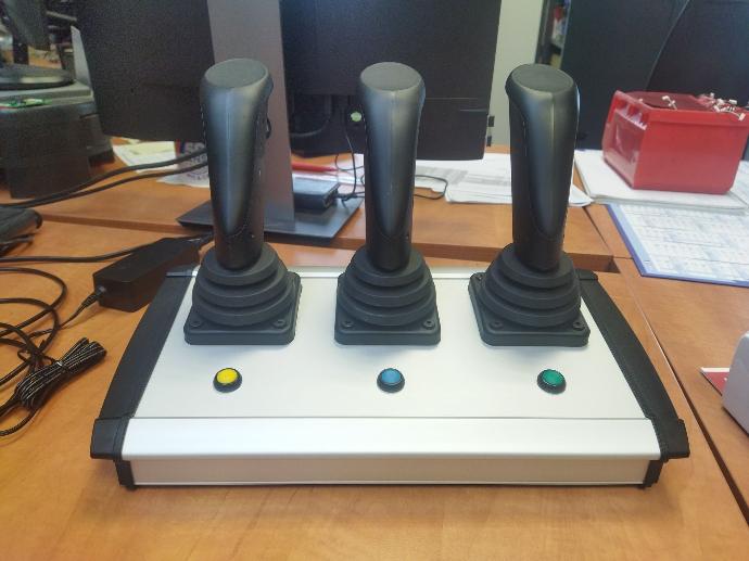
 Photo 1
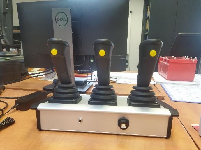 Photo 2
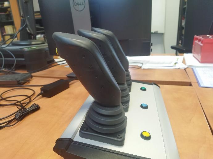 Photo 3
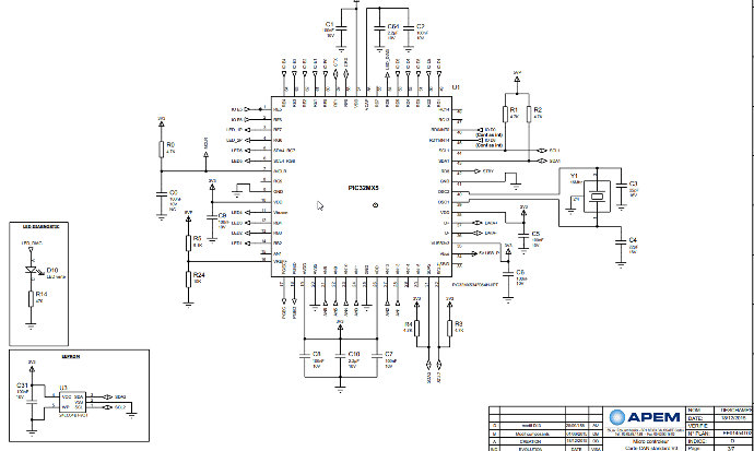

Programmation
Création d'un projet :
logiciel utilisé :
-MPLAB X IDE
-git
-picoscope

j'ai commençer par crée un projet sur git ce nommant : "Demo_manette_vibrante"
Avec MPLAB j'ai commencer a crée des sous dossier :
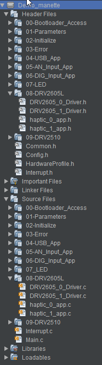
j'ai crée les sous dossier :
dans les header :
-08_DRV2605L
-DRV2605_0_Driver.h
-DRV2605_1_Driver.h
-haptic_0_app.h
-haptic_1_app.h
-09_DRV2510
dans le source :
08_DRV2605L
-DRV2605_0_Driver.c
-DRV2605_1_Driver.c
-haptic_0_app.c
-haptic_1_app.c
a noté que le DRV2605_0_Driver /DRV2605_1_Driver /haptic_0_app /haptic_1_app pour le 0 c'est pour l'I2C4 et le 1 pour l'I2C1 ( qui correspondent a un vibreur différent )
voici le DRV2605_0_Driver.h :
BOOL DRV2605_1_Driver_I2C_Idle(void);
BOOL DRV2605_1_Driver_I2C_TransmitOneByte(BYTE byData);
BOOL DRV2605_1_SendMsgToWrite(I2C_MODULE id, uint8_t regAddress, uint8_t *ptrData, uint8_t dataSize);
BYTE DRV2605_1_Driver_I2C_ReadOneByte(BYTE *ptr_value, BOOL is_last_byte);
BOOL DRV2605_1_Driver_I2C_StartTransfer(BOOL restart);
BOOL DRV2605_1_Driver_I2C_StopTransfer(void);
BOOL DRV2605_1_Driver_CheckAckStatusI2C(void);
BOOL DRV2605_1_Driver_I2C_ByteWasAcknowledged(I2C_MODULE id);
void DRV2605_1_Select_Waveform(uint8_t wav_frm_seq_reg_ad, uint8_t wav_frm_seq);
void DRV2605_1_Driver_Init(void);
void DRV2605_1_Driver_Go(void);
/** Descriptive File Name
@Company
APEM
@File Name
DRV2605_Driver.h
@Summary
Brief description of the file.
@Description
Describe the purpose of this file.
*/
/* ************************************************************************** */
#ifndef DRV2605_0_DRIVER_H
#define DRV2605_0_DRIVER_H
#include "Common.h"
#include <peripheral/i2c.h>
#include <GenericTypeDefs.h>
#include <stdint.h>
/*
* Defines
*/
#define USE_LED_I2C_TIMEOUT
#ifdef USE_LED_I2C_TIMEOUT
#define LED_I2C_TIMEOUT 100
#define LED_I2C_ACK_TIMEOUT 100
WORD wClock_LED_I2C_TimeOut;
WORD wClock_LED_I2C_Ack_TimeOut;
#endif
#define I2C_TIMEOUT 1000
/*
* DRV2605L register mapping
*/
#define DRV2605_REG_SIZE 0x22u
#define DRV2605_REG_00_AD 0x00u
#define DRV2605_REG_01_AD 0x01u
#define DRV2605_REG_02_AD 0x02u
#define DRV2605_REG_03_AD 0x03u
#define DRV2605_WAV_FRM_SEQ1_REG_AD 0x04u
#define DRV2605_WAV_FRM_SEQ2_REG_AD 0x05u
#define DRV2605_WAV_FRM_SEQ3_REG_AD 0x06u
#define DRV2605_WAV_FRM_SEQ4_REG_AD 0x07u
#define DRV2605_WAV_FRM_SEQ5_REG_AD 0x08u
#define DRV2605_WAV_FRM_SEQ6_REG_AD 0x09u
#define DRV2605_WAV_FRM_SEQ7_REG_AD 0x0Au
#define DRV2605_WAV_FRM_SEQ8_REG_AD 0x0Bu
#define DRV2605_GO_REG_AD 0x0Cu
#define DRV2605_ODT 0x0Du
#define DRV2605_SPT 0x0Eu
#define DRV2605_SNT 0x0Fu
#define DRV2605_BRT 0x10u
#define DRV2605_ATH 0x11u
#define DRV2605_ATH_MIN_INPUT 0x12u
#define DRV2605_ATH_MAX_INPUT 0x13u
#define DRV2605_ATH_MIN_DRIVE 0x14u
#define DRV2605_ATH_MAX_DRIVE 0x15u
#define DRV2605_RATED_VOLTAGE 0x16u
#define DRV2605_OD_CLAMP 0x17u
#define DRV2605_A_CAL_COMP 0x18u
#define DRV2605_A_CAL_BEMF 0x19u
#define DRV2605_N_ERM_LRA 0x1Au
#define DRV2605_STARTUP_BOOST 0x1Bu
#define DRV2605_BIDIR_INPUT 0x1Cu
#define DRV2605_NG_THRESH 0x1Du
#define DRV2605_ZC_DET_TIME 0x1Eu
#define DRV2605_AUTO_OL_CNT 0x1Fu
#define DRV2605_OL_LRA_PERIOD 0x20u
#define DRV2605_VBAT 0x21u
#define DRV2605_I2C_ADDRESS 0x5A
#define DRV2605_ADDRESS_WRITE 0xB4
#define DRV2605_ADDRESS_READ 0xB5
/* NULL */
#define SHARP_TICK1_100 24u
#define LONG_DOUBLE_SHARP_CLICK_STRONG 37u
/* MOINS NULL*/
#define MS_ALERT75 15u
#define MS_ALERT1s 16u
#define BUZZ_1 47u
/*
* Waveform Library Effects List
*/
#define STRONG_CLICK_100 1u
#define SOFT_BUMP_100 7u
#define STRONG_BUZZ_100 14u
#define SOFT_FUZZ_60 16u
#define STRONG_CLICK1_100 17u
#define MEDIUM_CLICK1_100 21u
#define PULSING_STRONG_1 52u
#define SHORT_DOUBLE_CLICK_MEDIUM1 31u
#define Long_Double_Sharp_Tick_1 44U
#define HAPTIC_BTN PULSING_STRONG_1
#define HAPTIC_VALID MS_ALERT1s
/*
* Prototypes
*/
BOOL DRV2605_0_Driver_I2C_Idle(void);
BOOL DRV2605_0_Driver_I2C_TransmitOneByte(BYTE byData);
BOOL DRV2605_0_SendMsgToWrite(I2C_MODULE id, uint8_t regAddress, uint8_t *ptrData, uint8_t dataSize);
BYTE DRV2605_0_Driver_I2C_ReadOneByte(BYTE *ptr_value, BOOL is_last_byte);
BOOL DRV2605_0_Driver_I2C_StartTransfer(BOOL restart);
BOOL DRV2605_0_Driver_I2C_StopTransfer(void);
BOOL DRV2605_0_Driver_CheckAckStatusI2C(void);
BOOL DRV2605_0_Driver_I2C_ByteWasAcknowledged(I2C_MODULE id);
void DRV2605_0_Select_Waveform(uint8_t wav_frm_seq_reg_ad, uint8_t wav_frm_seq);
void DRV2605_0_Driver_Init(void);
void DRV2605_0_Driver_Go(void);
#endif /* _DRV2605_0_DRIVER_H */
/* *****************************************************************************
End of File
*/
pour le DRV2605_1_Driver il n'y a que ça qui change :
BOOL DRV2605_1_Driver_I2C_Idle(void);
BOOL DRV2605_1_Driver_I2C_TransmitOneByte(BYTE byData);
BOOL DRV2605_1_SendMsgToWrite(I2C_MODULE id, uint8_t regAddress, uint8_t *ptrData, uint8_t dataSize);
BYTE DRV2605_1_Driver_I2C_ReadOneByte(BYTE *ptr_value, BOOL is_last_byte);
BOOL DRV2605_1_Driver_I2C_StartTransfer(BOOL restart);
BOOL DRV2605_1_Driver_I2C_StopTransfer(void);
BOOL DRV2605_1_Driver_CheckAckStatusI2C(void);
BOOL DRV2605_1_Driver_I2C_ByteWasAcknowledged(I2C_MODULE id);
void DRV2605_1_Select_Waveform(uint8_t wav_frm_seq_reg_ad, uint8_t wav_frm_seq);
void DRV2605_1_Driver_Init(void);
void DRV2605_1_Driver_Go(void);
pour le haptic_0_app.h :
/** Descriptive File Name
@Company
APEM
@File Name
haptic_0_app.h
@Summary
Brief description of the file.
@Description
Describe the purpose of this file.
*/
/* ************************************************************************** */
#ifndef HAPTIC_0_APP_H_
#define HAPTIC_0_APP_H_
/*
* Prototypes
*/
void Haptic_0_App_Init(void);
void Haptic_0_App_Task(void);
void Haptic_0_App_Go(void);
void Haptic_0_App_Set_Valid(void);
void Haptic_0_App_Set_Btn(void);
void Haptic_0_App_Go_Valid(void);
#endif /* HAPTIC_0_APP_H_ */
/*
End of File
*/
ce qui change pour le haptic_1_app.h :
void Haptic_1_App_Init(void);
void Haptic_1_App_Task(void);
void Haptic_1_App_Go(void);
void Haptic_1_App_Set_Valid(void);
void Haptic_1_App_Set_Btn(void);
void Haptic_1_App_Go_Valid(void);
ensuite nous avons le DRV2605_0_Driver.c et le DRV2605_1_Driver.c
la seule chose qui change sont les 0 ou les 1 pour DRV2605_0_Driver.c :
/* Descriptive File Name
@Company
APEM
@File Name
DRV2605_0_driver.c
*/
#include <plib.h>
#include <string.h>
#include <GenericTypeDefs.h>
#include <peripheral/i2c.h>
#include "Initialize.h"
#include "HardwareProfile.h"
#include "DRV2605_0_Driver.h"
extern volatile UINT16 u16_clock1ms;
static void DRV2605_0_Remove_Standby_Mode(void);
/*prototype*/
BOOL InitI2C_0();
/********************************************************************
* Function: DRV2605_0_Driver_I2C_Idle
*
* Precondition:
*
* Input: None.
*
* Output: BOOL : TRUE if in idle state, FALSE instead
*
* Side Effects:
*
* Overview: Check if the I2C is in idle situation.
*
* Note:
********************************************************************/
BOOL DRV2605_0_Driver_I2C_Idle(void) {
#ifdef USE_LED_I2C_TIMEOUT
wClock_LED_I2C_TimeOut = u16_clock1ms + LED_I2C_TIMEOUT;
#endif
while (I2C4CONbits.SEN || I2C4CONbits.PEN || I2C4CONbits.RSEN || I2C4CONbits.RCEN || I2C4CONbits.ACKEN || I2C4STATbits.TRSTAT) {
#ifdef USE_LED_I2C_TIMEOUT
if (TIME_OVER(wClock_LED_I2C_TimeOut, u16_clock1ms)) {
return FALSE;
}
#else
Nop();
#endif
}
return TRUE;
}
/********************************************************************
* Function: DRV2605_Driver_InitI2C
*
* Precondition:
*
* Input: None.
*
* Output: BOOL = true if init ok
*
* Side Effects:
*
* Overview: Init TLC register according to TLC datasheet
*
* Note: Initialize I2C peripherical
********************************************************************/
BOOL InitI2C_0(void) {
BOOL bl_ret = FALSE;
// Initialisation de l'I2C pour U2
I2C_SDA_2605_0_Odc = 0;
I2C_SCL_2605_0_Odc = 0;
EN2605_0_Odc = 0;
OC1_Odc = 0;
I2C_SDA_2605_0_Tris = 0;
I2C_SCL_2605_0_Tris = 0;
EN2605_0_Tris = 0;
OC1_Tris = 0;
EN2605_0_Lat = 0;
EN2605_0_Lat = 1;
I2CSetFrequency(I2C4, GetPeripheralClock(), I2C4_CLOCK_FREQ);
I2CConfigure(I2C4, I2C_STOP_IN_IDLE | I2C_ENABLE_HIGH_SPEED);
I2CEnable(I2C4, TRUE);
// bl_ret = DRV2605_Driver_CheckAckStatusI2C();
return bl_ret;
}
/********************************************************************
* Function: DRV2605_0_Driver_I2C_TransmitOneByte
*
* Precondition: The transfer must have been previously started.
*
* Input: BYTE data = Data byte to transmit
*
* Output: BOOL = TRUE - Data was sent successfully
FALSE - A bus collision occured
*
* Side Effects:
*
* Overview: Transmits one byte to the TLC Driver led, and reports errors for any bus
* collisions.
*
* Note: This is a blocking routine that waits for the
* transmission to complete if timeout not defined
********************************************************************/
BOOL DRV2605_0_Driver_I2C_TransmitOneByte(BYTE byData) {
if (DRV2605_0_Driver_I2C_Idle()) {
/* Wait for the transmitter to be ready */
#ifdef USE_LED_I2C_TIMEOUT
/* Arm the timer */
wClock_LED_I2C_TimeOut = u16_clock1ms + LED_I2C_TIMEOUT;
#endif
while (!I2CTransmitterIsReady(I2C4)) {
#ifdef USE_LED_I2C_TIMEOUT
if (TIME_OVER(wClock_LED_I2C_TimeOut, u16_clock1ms)) {
return FALSE;
}
#else
Nop();
#endif
}
/* Transmit the byte */
if (I2CSendByte(I2C4, byData) != I2C_SUCCESS) {
/* I2C Master Bus Collision" */
return FALSE;
}
#ifdef USE_LED_I2C_TIMEOUT
/* Arm the timer */
wClock_LED_I2C_TimeOut = u16_clock1ms + LED_I2C_TIMEOUT;
#endif
/* Wait for the transmission to finish */
while (!I2CTransmissionHasCompleted(I2C4)) {
#ifdef USE_LED_I2C_TIMEOUT
if (TIME_OVER(wClock_LED_I2C_TimeOut, u16_clock1ms)) {
return FALSE;
}
#else
Nop();
#endif
}
return TRUE;
} else {
return FALSE;
}
}
/********************************************************************
* Function: DRV2605_0_SendMsgToWrite
*
* Precondition:
*
* Input:
*
* Output:
*
* Side Effects:
*
* Overview:
*
* Note:
********************************************************************/
BOOL DRV2605_0_SendMsgToWrite(I2C_MODULE id, uint8_t regAddress, uint8_t *ptrData, uint8_t dataSize) {
I2C_7_BIT_ADDRESS SlaveAddress;
I2C_FORMAT_7_BIT_ADDRESS(SlaveAddress, DRV2605_I2C_ADDRESS, I2C_WRITE);
I2CClearStatus(I2C4, I2C_BYTE_ACKNOWLEDGED);
// Start Condition on I2C bus
if (!DRV2605_0_Driver_I2C_StartTransfer(FALSE)) {
return FALSE;
}
// Send Address on I2C bus
if (!DRV2605_0_Driver_I2C_TransmitOneByte(SlaveAddress.byte)) {
return FALSE;
}
#ifdef USE_LED_I2C_TIMEOUT
wClock_LED_I2C_TimeOut = u16_clock1ms + LED_I2C_TIMEOUT;
#endif
// Attendre l'acknowledgement
while (!I2CByteWasAcknowledged(I2C4)) {
#ifdef USE_LED_I2C_TIMEOUT
if (TIME_OVER(wClock_LED_I2C_TimeOut, u16_clock1ms)) {
return FALSE;
}
#else
Nop();
#endif
}
// Envoyer l'adresse du registre
if (!DRV2605_0_Driver_I2C_TransmitOneByte(regAddress)) {
return FALSE;
}
#ifdef USE_LED_I2C_TIMEOUT
wClock_LED_I2C_TimeOut = u16_clock1ms + LED_I2C_TIMEOUT;
#endif
// Attendre l'acknowledgement
while (!I2CByteWasAcknowledged(I2C4)) {
#ifdef USE_LED_I2C_TIMEOUT
if (TIME_OVER(wClock_LED_I2C_TimeOut, u16_clock1ms)) {
return FALSE;
}
#else
Nop();
#endif
}
// Envoyer les données
uint8_t i;
for (i = 0; i < dataSize; i++) {
if (!DRV2605_0_Driver_I2C_TransmitOneByte(ptrData[i])) {
return FALSE;
}
}
// Fin de la transmission (arrêt si une erreur est survenue)
if (!DRV2605_0_Driver_I2C_StopTransfer()) {
return FALSE;
}
return TRUE;
}
/********************************************************************
* Function: DRV2605_0_Driver_I2C_ReadOneByte
*
* Precondition:
*
* Input:
*
* Output: BYTE = value from TLC59116_Driver
*
* Side Effects:
*
* Overview: Read the Data in EEPROM at the specified Address
*
* Note: Check TLC59116_Driver_CheckAckStatusI2C before re-used
********************************************************************/
BYTE DRV2605_0_Driver_I2C_ReadOneByte(BYTE *ptr_value, BOOL is_last_byte) {
// Assurez-vous que le bus I2C est disponible
if (DRV2605_0_Driver_I2C_Idle()) {
// Activez le récepteur I2C
if (I2CReceiverEnable(I2C4, TRUE) != I2C_RECEIVE_OVERFLOW) {
// Attendez que les données soient disponibles sur le bus I2C
while (!I2CReceivedDataIsAvailable(I2C4)) {
#ifdef USE_LED_I2C_TIMEOUT
// Vérifiez le dépassement du temps d'attente
if (TIME_OVER(wClock_LED_I2C_TimeOut, u16_clock1ms)) {
return FALSE;
}
#else
// Ajoutez une légère pause pour permettre la réception des données
Nop();
#endif
}
// Confirmez la réception de l'octet
if (!is_last_byte) {
I2CAcknowledgeByte(I2C4, TRUE);
while (!I2CAcknowledgeHasCompleted(I2C4)) {
// Attendez la fin de la confirmation de l'octet
}
}
// Lisez l'octet du bus I2C
*ptr_value = (BYTE) I2CGetByte(I2C4);
// Effacez le statut de données disponibles
I2CClearStatus(I2C4, I2C_DATA_AVAILABLE);
// Indiquez que la lecture a réussi
return TRUE;
} else {
// Le récepteur I2C a rencontré un problème, retournez FALSE
return FALSE;
}
} else {
// Le bus I2C n'est pas disponible, retournez FALSE
return FALSE;
}
}
/********************************************************************
* Function: DRV2605_0_Driver_I2C_StartTransfer
*
* Precondition: The I2C module must have been initialized.
*
* Input: - If FALSE, send a "Start" condition
* - If TRUE, send a "Restart" condition
*
* Output: - TRUE - If successful
* - FALSE - If a collision occured during Start signaling
*
* Side Effects: Starts (or restarts) a transfer to the LED driver.
*
* Overview: This routine starts (or restarts) a transfer to the LED driver,
* waiting (in a blocking loop) until the start (or re-start) condition
* has completed.
*
* Note: This is a blocking routine that waits for the bus to be
* idle and the Start (or Restart) signal to complete.
********************************************************************/
BOOL DRV2605_0_Driver_I2C_StartTransfer(BOOL restart) {
I2C_STATUS status;
// Assurez-vous que le bus I2C est en attente
if (!DRV2605_0_Driver_I2C_Idle()) {
return FALSE;
}
// Envoyer le signal de démarrage (ou de redémarrage)
if (restart) {
// Redémarrer la communication I2C
if (I2CRepeatStart(I2C4) /*!= I2C_SUCCESS*/) {
return FALSE; // En cas d'échec du redémarrage
}
} else {
// Vérifier si le bus I2C est déjà occupé
if (!I2CBusIsIdle(I2C4)) {
return FALSE; // En cas d'occupation du bus
}
// Démarrer la communication I2C
if (I2CStart(I2C4) != I2C_SUCCESS) {
return FALSE; // En cas d'échec du démarrage
}
}
#ifdef USE_LED_I2C_TIMEOUT
// Configuration du délai d'attente pour le signal de démarrage
wClock_LED_I2C_TimeOut = u16_clock1ms + LED_I2C_TIMEOUT;
#endif
// Attendre que le signal de démarrage soit complet
do {
status = I2CGetStatus(I2C4);
if (I2C_ARBITRATION_LOSS & status) {
I2CClearStatus(I2C4, I2C_ARBITRATION_LOSS);
DRV2605_0_Driver_I2C_Idle();
I2CStart(I2C4);
}
#ifdef USE_LED_I2C_TIMEOUT
if (TIME_OVER(wClock_LED_I2C_TimeOut, u16_clock1ms)) {
return FALSE; // En cas de dépassement du délai d'attente
}
#endif
} while (!(status & I2C_START));
// Vérifier si le bus est à nouveau en attente après le démarrage
return DRV2605_0_Driver_I2C_Idle();
}
/********************************************************************
* Function: DRV2605_0_Driver_I2C_StopTransfer
*
* Precondition: The I2C module must have been initialized & a
* transfer started.
*
* Input: None.
*
* Output: BOOL = true if ok otherwise false.
*
* Side Effects: Stops a transfer to the LED driver.
*
* Overview: This routine Stops a transfer to the LED Driver, waiting
* (in a blocking loop) until the Stop condition has completed.
*
* Note: This is a blocking routine that waits for the Stop signal to complete
* if timeout not defined
********************************************************************/
BOOL DRV2605_0_Driver_I2C_StopTransfer(void) {
I2C_STATUS status;
/* Send the Stop signal */
I2CStop(I2C4);
/* Wait for the signal to complete */
#ifdef USE_LED_I2C_TIMEOUT
/* Arm the timer */
wClock_LED_I2C_TimeOut = u16_clock1ms + LED_I2C_TIMEOUT;
#endif
do {
status = I2CGetStatus(I2C4);
if (I2C_ARBITRATION_LOSS & status) {
I2CClearStatus(I2C4, I2C_ARBITRATION_LOSS);
DRV2605_0_Driver_I2C_Idle();
I2CStop(I2C4);
}
#ifdef USE_LED_I2C_TIMEOUT
if (TIME_OVER(wClock_LED_I2C_TimeOut, u16_clock1ms)) {
return FALSE;
}
#endif
} while (!(status & I2C_STOP));
return DRV2605_0_Driver_I2C_Idle();
}
/********************************************************************
* Function: DRV2605_0_CheckAckStatusI2C
*
* Precondition:
*
* Input: None.
*
* Output: BOOL = TRUE if Ack ok FALSE instead
*
* Side Effects:
*
* Overview: Verify if the TLC59116 Ack the last command
*
* Note:
********************************************************************/
BOOL DRV2605_0_Driver_CheckAckStatusI2C(void) {
BOOL Success = TRUE;
BOOL Acknowledged;
I2C_7_BIT_ADDRESS SlaveAddress;
I2C_FORMAT_7_BIT_ADDRESS(SlaveAddress, DRV2605_I2C_ADDRESS, I2C_WRITE);
Acknowledged = FALSE;
#ifdef USE_LED_I2C_TIMEOUT
/* Arm the ACK timeout */
wClock_LED_I2C_Ack_TimeOut = u16_clock1ms + LED_I2C_ACK_TIMEOUT;
#endif
do {
/* Start the transfer to address the I2C LED Drive */
if (!DRV2605_0_Driver_I2C_StartTransfer(FALSE)) {
return FALSE;
}
/* Transmit just the LED Driver's address */
if (DRV2605_0_Driver_I2C_TransmitOneByte(SlaveAddress.byte)) {
/* Check to see if the byte was acknowledged */
Acknowledged = I2CByteWasAcknowledged(I2C4);
}
#ifdef USE_LED_I2C_TIMEOUT
if (TIME_OVER(wClock_LED_I2C_Ack_TimeOut, u16_clock1ms)) {
return FALSE;
}
#endif
/* End the transfer (stop here if an error occured) */
if (!DRV2605_0_Driver_I2C_StopTransfer()) {
return FALSE;
}
} while (Acknowledged != TRUE);
return Success;
}
/********************************************************************
* Function: DRV2605_0_Driver_I2C_ByteWasAcknowledged
*
* Precondition:
*
* Input: I2C_MODULE id lise : I2C1 or IC2C2 ...
*
* Output: BOOL = true if ok otherwise false.
*
* Side Effects:
*
* Overview: Check if byte was acknowledged
*
* Note:
********************************************************************/
BOOL DRV2605_0_Driver_I2C_ByteWasAcknowledged(I2C_MODULE id) {
/* Check to see if the byte was acknowledged */
I2CByteWasAcknowledged(I2C4);
#ifdef USE_LED_I2C_TIMEOUT
if (TIME_OVER(wClock_LED_I2C_Ack_TimeOut, u16_clock1ms)) {
return FALSE;
}
#endif
return TRUE;
}
/********************************************************************
* Function: DRV2605_0_Select_Waveform
*
* Precondition:
*
* Input: uint8_t wav_frm_seq_reg_ad : register add like DRV2605L_WAV_FRM_SEQ1_REG_AD
* uint8_t wav_frm_seq : register sequence possible value 0-6
*
* Output:
*
* Side Effects:
*
* Overview:
*
* Note:
********************************************************************/
void DRV2605_0_Select_Waveform(uint8_t wav_frm_seq_reg_ad, uint8_t wav_frm_seq) {
DRV2605_0_SendMsgToWrite(I2C4, wav_frm_seq_reg_ad, &wav_frm_seq, 1u);
}
/********************************************************************
* Function: DRV2605_0_Remove_Standby_Mode
*
* Precondition:
*
* Input:
*
* Output:
*
* Side Effects:
*
* Overview:
*
* Note:
********************************************************************/
static void DRV2605_0_Remove_Standby_Mode(void) {
/* DEV_RESET - 0: Device reset. */
/* STANDBY - 0:Device ready */
/* MODE - 0: Internal trigger */
uint8_t resetReg = 0u;
DRV2605_0_SendMsgToWrite(I2C4, DRV2605_REG_01_AD, &resetReg, 1u);
}
/********************************************************************
* Function: DRV2605_0_Driver_Init
*
* Precondition:
*
* Input:
*
* Output:
*
* Side Effects:
*
* Overview:
*
* Note:
********************************************************************/
void DRV2605_0_Driver_Init(void) {
InitI2C_0();
/* Initialization Procedure */
/* EN pin is set by default at high */
/* Write MODE register 0x01 to 0x00 */
DRV2605_0_Remove_Standby_Mode();
DRV2605_0_Select_Waveform(DRV2605_WAV_FRM_SEQ1_REG_AD, 0x00u);
DRV2605_0_Select_Waveform(DRV2605_WAV_FRM_SEQ2_REG_AD, 0x00u);
DRV2605_0_Select_Waveform(DRV2605_WAV_FRM_SEQ3_REG_AD, 0x00u);
DRV2605_0_Select_Waveform(DRV2605_WAV_FRM_SEQ4_REG_AD, 0x00u);
DRV2605_0_Select_Waveform(DRV2605_WAV_FRM_SEQ5_REG_AD, 0x00u);
DRV2605_0_Select_Waveform(DRV2605_WAV_FRM_SEQ6_REG_AD, 0x00u);
DRV2605_0_Select_Waveform(DRV2605_WAV_FRM_SEQ7_REG_AD, 0x00u);
DRV2605_0_Select_Waveform(DRV2605_WAV_FRM_SEQ8_REG_AD, 0x00u);
// DRV2605_Driver_I2C_ReadOneByte();
DRV2605_0_Driver_Go();
}
/********************************************************************
* Function: DRV2605_0_Driver_Go
*
* Precondition:
*
* Input:
*
* Output:
*
* Side Effects:
*
* Overview:
*
* Note:
********************************************************************/
void DRV2605_0_Driver_Go(void) {
uint8_t u8_Go = 1u;
DRV2605_0_SendMsgToWrite(I2C4, DRV2605_GO_REG_AD, &u8_Go, 1u);
}
/* *****************************************************************************
End of File
*/
et pour le haptic_0_app.c et haptic_1_app.c c'est la même chose soit 0 soit 1 qui change :
/** Descriptive File Name
@Company
APEM
@File Name
haptic_0_app.c
@Summary
Brief description of the file.
@Description
Describe the purpose of this file.
*/
/* ************************************************************************** */
/* ************************************************************************** */
/* Section: Included Files */
/* ************************************************************************** */
/* ************************************************************************** */
#include "haptic_0_app.h"
#include "common.h"
#include "DRV2605_0_Driver.h"
/********************************************************************
* Function: Haptic_App_Init
*
* Input:
*
* Output:
*
* Side Effects:
*
* Overview:
*
* Note:
********************************************************************/
void Haptic_0_App_Init(void) {
DRV2605_0_Driver_Init();
DRV2605_0_Select_Waveform(DRV2605_WAV_FRM_SEQ1_REG_AD, WAVEFORM_HAPTIC_BTN);
}
/********************************************************************
* Function: Haptic_App_Go
*
* Input:
*
* Output:
*
* Side Effects:
*
* Overview:
*
* Note:
********************************************************************/
void Haptic_0_App_Go(void)
{
DRV2605_0_Driver_Go();
}
/********************************************************************
* Function: Haptic_App_Set_Valid
*
* Input:
*
* Output:
*
* Side Effects:
*
* Overview:
*
* Note:
********************************************************************/
void Haptic_0_App_Set_Valid(void) {
DRV2605_0_Select_Waveform(DRV2605_WAV_FRM_SEQ1_REG_AD, WAVEFORM_HAPTIC_VALID);
}
/********************************************************************
* Function: Haptic_App_Set_Btn
*
* Input:
*
* Output:
*
* Side Effects:
*
* Overview:
*
* Note:
********************************************************************/
void Haptic_0_App_Set_Btn(void) {
DRV2605_0_Select_Waveform(DRV2605_WAV_FRM_SEQ1_REG_AD, WAVEFORM_HAPTIC_BTN);
}
/********************************************************************
* Function: Haptic_App_Go_Valid
*
* Input:
*
* Output:
*
* Side Effects:x
*
* Overview:
*
* Note:
********************************************************************/
void Haptic_0_App_Go_Valid(void) {
Haptic_0_App_Set_Valid();
Haptic_0_App_Go();
Haptic_0_App_Set_Btn();
}
/********************************************************************
* Function: Haptic_App_Task
*
* Input:
*
* Output:
*
* Side Effects:
*
* Overview:
*
* Note:
********************************************************************/
void Haptic_0_App_Task(void) {
}
/* *****************************************************************************
End of File
*/
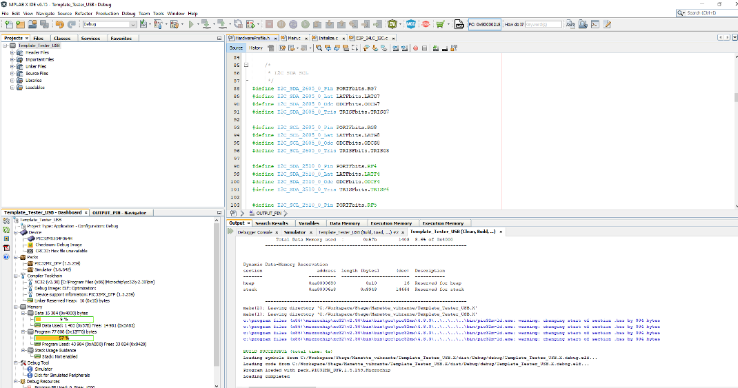
ensuite comment on l'utilise dans le main :
int main(void) {
/* Reset TickSystem */
u16_clock1ms = 0;
/* Initialize µC */
InitializePIC();
/* Initialize USB */
#ifdef USB_ACTIVE
InitializeUSB(); /* enable USB module and initialize registers */
#ifdef USB_INTERRUPT
USBDeviceAttach(); /* enable interrupts and initialize them */
#endif
#endif
/* To change the USB Product string descriptor */
/* go to this file */
/* usb_descriptions.c */
/* and change the sd002 */
/* Unlock the bootloader */
EraseLastRequester(BTL_SENDER_ID);
/* WDT timeout period is set in the Device Configuration */
DisableWDT();
if (ReadEventWDT()) { /* A WDT event did occur */
DisableWDT();
ClearEventWDT(); /* clear the WDT event flag so a subsequent event can set the event bit */
}
EnableWDT();
Haptic_0_App_Init();
Haptic_0_App_Set_Btn();
Haptic_1_App_Init();
Haptic_1_App_Set_Btn();
while (1) {
ClearWDT();
#ifdef USB_ACTIVE
#ifdef USB_POLLING
USBDeviceTasks(); /* detect current status of USB module and handle it */
#endif
USB_RECEIVE_DATA();
if (BTN2_Port != 1 || BTN5_Port != 1) {
DRV2605_0_Driver_Go();
delay_us(2500);
}
if (BTN1_Port != 1 || BTN4_Port != 1) {
DRV2605_1_Driver_Go();
delay_us(2500);
}
if (BTN0_Port != 1 || BTN3_Port != 1) {
}
}
#endif
}
utilisation du picoscope

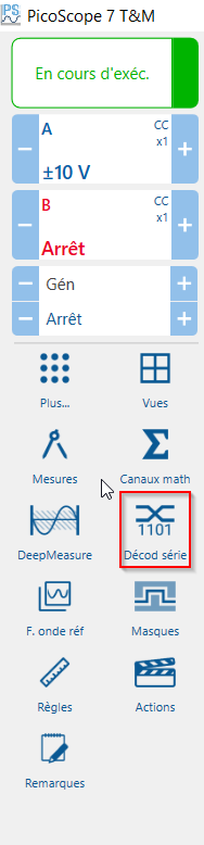
démarrage du logiciel picoscope
choix de l'appareil
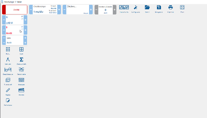
Page d'accueil
une fois l'appareil détecter on arrive ici

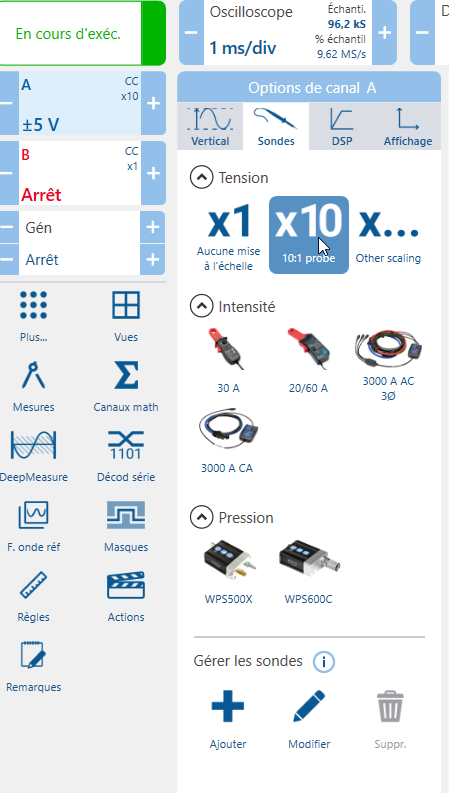
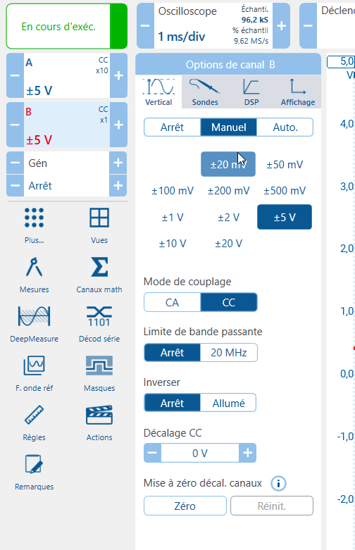
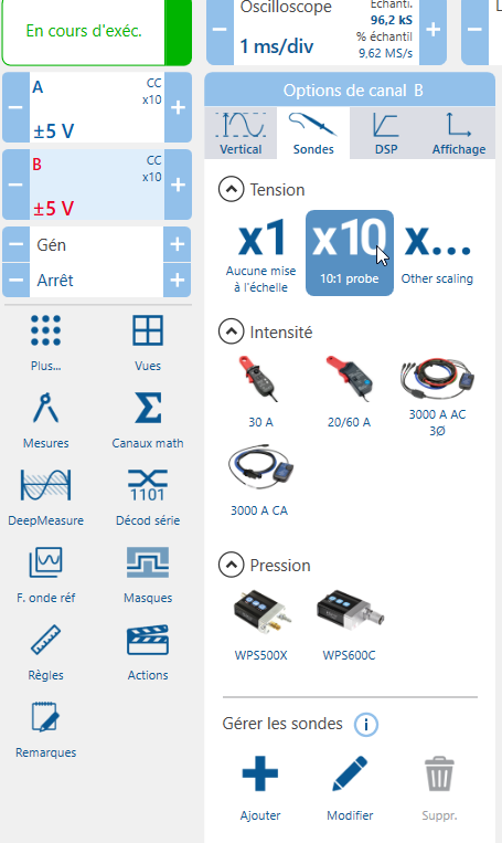

ceci est la configuration de la mise en tension.
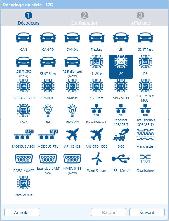
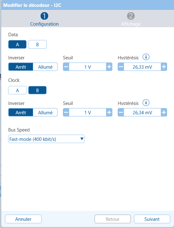
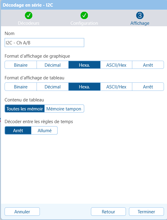
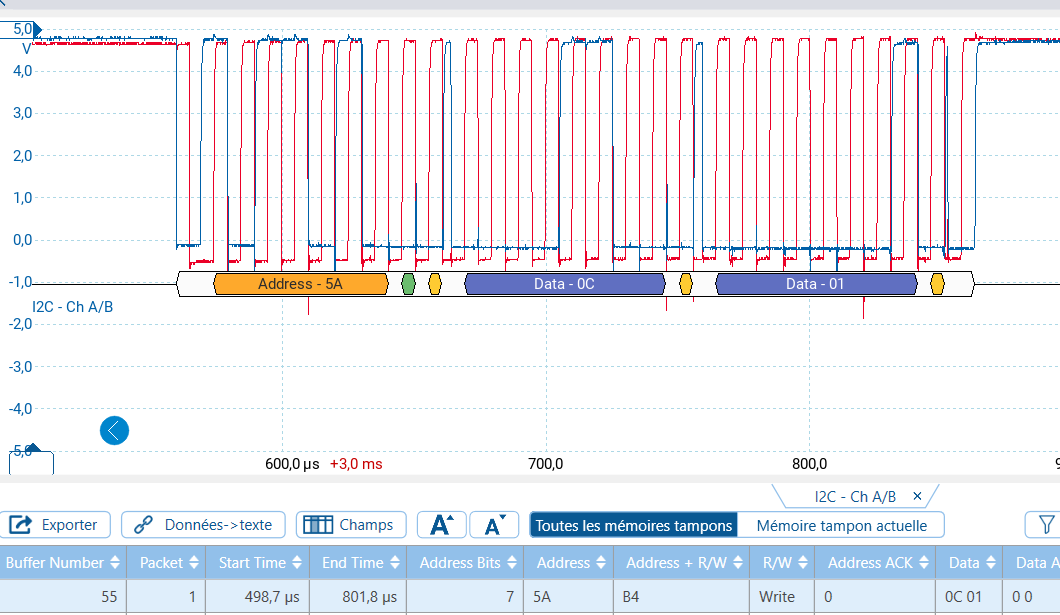
Voici comment paramétrer l'I2C (avec un exemple)
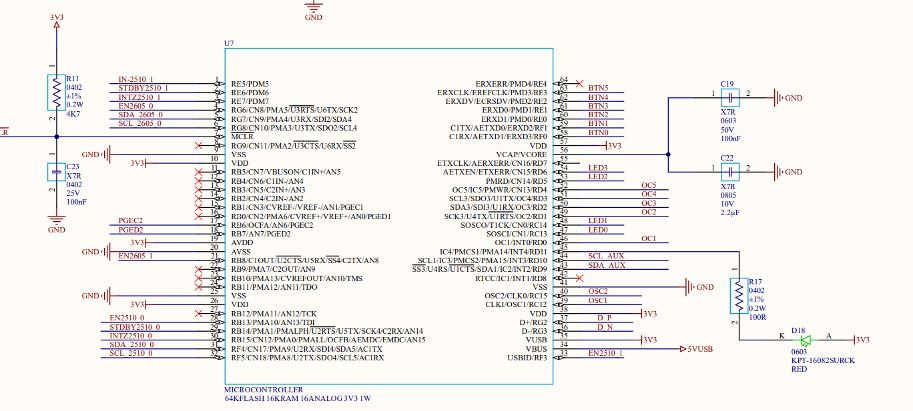
Schéma des vibreurs
Confidentialité apem